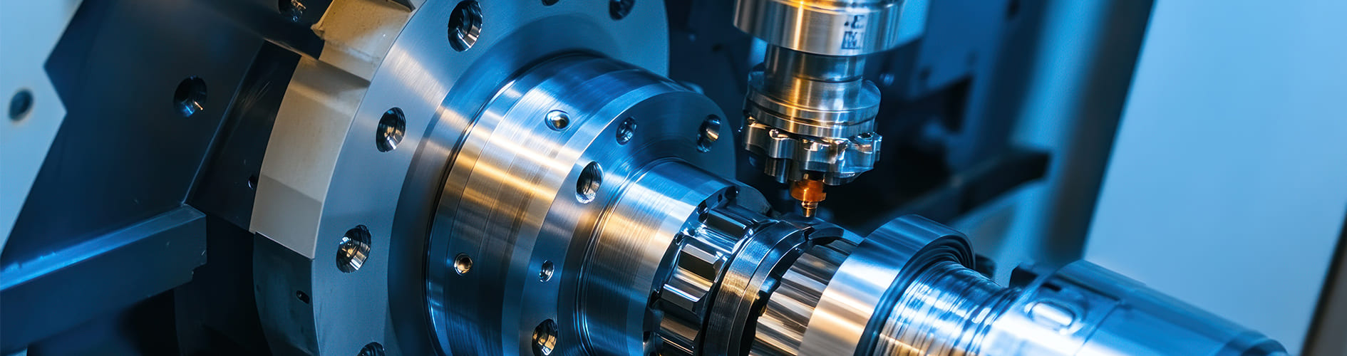
A milling machine is the most versatile machine tool in most workshops, and also the one most often bought badly. The problem is that a vertical knee mill, a bed type machine and a double column bridge mill all cut metal with a rotating cutter, yet they are built for entirely different jobs. This guide explains what a milling machine is, the cutting mechanics that separate a good result from a ruined cutter, the main types of milling machines, how different industries use them, and the specification checks that matter before you buy.
What Is a Milling Machine?
A milling machine is a machine tool that removes material with a rotating multi-tooth cutter while the workpiece is held stationary on a table and moved along controlled axes. It is the standard route to flat faces, square shoulders, slots, pockets, contours and accurately positioned holes — in short, to almost every part that is not round.
The contrast with turning is the clearest way to understand it. On a lathe the workpiece rotates and the tool stays still, which naturally generates circles. On a milling machine the tool rotates and the workpiece stays still, which naturally generates planes and prismatic shapes. That difference also creates milling's defining characteristic: the cut is interrupted. Each tooth enters the material, removes a comma-shaped chip, leaves, cools in air, then enters again — often thousands of times a minute.
Almost everything distinctive about milling follows from that interruption. Every tooth entry is a mechanical shock, so cutter material and edge preparation matter enormously. The cyclic loading excites vibration, which is why milling machines are built heavy and why chatter is the process's signature failure mode. And because each tooth only cuts part of the time, heat is pulsed rather than continuous — which is why coolant strategy in milling is a genuine engineering decision rather than a habit.
The Mechanics of Milling: What Actually Governs the Result
Most milling problems — premature tool failure, chatter, poor finish, cutters that seem to rub instead of cut — come down to the four points below. They are worth more than any brochure specification.
Climb Milling vs Conventional Milling
This is the single most important concept in milling, and the one most often misunderstood. The difference is the direction the cutter rotates relative to the direction the table feeds.
In conventional (up) milling, the tooth enters the cut at zero chip thickness and exits at maximum. Because it cannot bite at zero thickness, the tooth rubs and burnishes the surface before it starts cutting. That rubbing generates heat, work-hardens the material ahead of the next tooth, and wears the edge quickly.
In climb (down) milling, the tooth enters at maximum chip thickness and exits at zero. The edge bites immediately, cutting forces press the workpiece down onto the table rather than lifting it, heat goes into the chip instead of the part, and both surface finish and tool life improve substantially.
Climb milling is therefore the default on any modern machine — with one critical exception. Climb milling pulls the table in the direction of feed. On a machine with worn lead screws and backlash, that pull snatches the table forward into the cutter, which at best breaks the tool and at worst is genuinely dangerous. This is why older manual machines are often run conventionally, and why a backlash-eliminator or preloaded ball screws are not a luxury on a machine you intend to climb mill with.
Feed per Tooth Is the Number That Matters
Table feed in mm/min tells you almost nothing on its own. The meaningful quantity is feed per tooth (fz) — how much material each individual cutting edge takes:
vf = fz × z × n
(vf = table feed in mm/min, fz = feed per tooth in mm, z = number of teeth, n = spindle speed in rpm)
The practical consequence catches people out constantly. Swap a 2-flute end mill for a 4-flute at the same table feed and spindle speed, and you have just halved the chip each tooth takes — the cutter now rubs rather than cuts, and it will wear out faster despite working "less hard". To keep the same chip load you must double the table feed. Conversely, a cutter with more teeth is the correct way to increase metal removal rate without increasing the load on any single edge.
Chip Thinning: Why Light Side Cuts Destroy Cutters
Here is a fact that surprises many experienced machinists. When the radial engagement (ae) is less than half the cutter diameter, the actual chip produced is thinner than the programmed feed per tooth, because the tooth is sweeping a shallow arc rather than a full quarter turn. At 10% radial engagement, the real chip thickness is roughly a third of fz.
The consequence is counter-intuitive but important: a light finishing pass at normal feed makes the cutter rub, not cut. Rubbing generates heat without removing metal, which is the fastest way to destroy a coated carbide edge. The correct response is to increase feed per tooth as radial engagement falls — the principle behind high-efficiency and trochoidal milling strategies, which take a small radial bite at a high feed and a deep axial depth. If your finishing passes wear cutters faster than your roughing passes, this is almost always why.
Tool Overhang and the Cube Rule
Deflection of a cutter or holder increases with the cube of its unsupported length. Doubling the overhang does not double the deflection — it increases it roughly eightfold. A cutter that chatters at 60 mm of stick-out may cut perfectly at 40 mm. Before changing speeds, feeds or tooling brands to solve a chatter problem, shorten the tool. It is free, and it is usually the answer.
Keeping Teeth in the Cut
Stability also depends on how many teeth are engaged at any instant. If engagement drops so low that each tooth leaves the cut before the next enters, the spindle load pulses on and off and the machine is excited at exactly its worst frequency. Face milling is generally smoothest when the cutter is offset so the workpiece sits slightly off the cutter centreline rather than symmetrically beneath it — this controls the entry and exit angles and keeps engagement more even.
Key Parts of a Milling Machine
- Base and column — the structural backbone carrying all cutting loads to the floor.
- Spindle — holds and drives the cutter; its taper (BT, CAT, HSK, NT) defines the tooling system.
- Head — carries the spindle; may be fixed, tilting, or of the ram-and-turret type on a knee mill.
- Knee — on knee-type machines, the vertically adjustable casting supporting the saddle and table.
- Saddle — provides cross (Y axis) movement between knee and table.
- Table — the T-slotted surface that carries the workpiece and provides longitudinal (X axis) travel.
- Overarm and arbor support — on horizontal machines, supports the far end of the cutter arbor.
- Ball screws and guideways — convert motor rotation into precise axis motion; box ways favour damping, linear guides favour speed.
- Automatic tool changer (ATC) — on CNC machines, swaps tools without operator intervention.
- Coolant system — flood, through-spindle or mist delivery to the cutting zone.
- Control — from a simple digital readout on a manual machine to a full CNC with look-ahead.
What Can a Milling Machine Do?
- Face milling — producing a large flat surface with the face of the cutter.
- Peripheral and shoulder milling — cutting square steps and side walls with the cutter's flank.
- Slotting and keyway cutting — producing channels with an end mill or slot drill.
- Pocketing — clearing enclosed cavities, the backbone of mould and die work.
- Drilling, boring and tapping — hole making at precisely controlled positions.
- Contour and profile milling — following a 2D or 3D path to generate curved forms.
- Gear and form cutting — using a form cutter on a horizontal machine with a dividing head.
- Engraving and chamfering — fine detail and edge-breaking with small-diameter tooling.
The Types of Milling Machines
Milling machines are classified first by spindle orientation and second by how the workpiece is supported. Those two choices decide the machine's rigidity, its working envelope and the kind of work it suits.
1. Vertical Milling Machine (Knee Type)
The vertical milling machine has the spindle axis perpendicular to the table, so the cutter points down at the work. On a knee-type machine the table sits on a saddle, which sits on a vertically adjustable knee — giving three axes of hand or powered movement with the operator standing directly at the work.
This is the machine most people picture when they hear "mill", and it dominates toolrooms for good reasons. The cutter and the cut are fully visible. Setup is quick, since a vice bolts to the table and a part can be dialled in with an indicator in minutes. And the ram-and-turret head found on many models swivels and nods, letting the operator reach angled faces without special fixtures. A compact knee-type vertical mill is often the single most useful machine in a small shop.
The limitation is rigidity. The knee is a cantilever, and raising it extends that cantilever further. Heavy cuts on a knee mill provoke chatter long before the spindle motor runs out of power, and the higher the knee, the worse it gets.
Best for: toolrooms, prototypes, jigs and fixtures, maintenance work, short runs and training.
2. Horizontal Milling Machine
A horizontal milling machine carries the spindle parallel to the table, with cutters mounted on an arbor supported at both ends by an overarm. That double support is the entire point: an arbor held at two ends deflects far less than a cutter cantilevered from a vertical spindle, so a horizontal machine removes metal at rates a vertical mill cannot approach.
It also allows gang milling — several cutters on one arbor machining multiple surfaces in a single table pass. For a run of castings needing three parallel faces, a horizontal mill set up once will outproduce a vertical machine many times over. Chips also fall away from the cut rather than collecting in it, which matters in deep slots.
Best for: heavy stock removal, slotting and gang milling, gear and form cutting with a dividing head, and repeat production of prismatic parts.
3. Vertical and Horizontal (Combination) Milling Machine
A vertical and horizontal milling machine provides both spindle orientations on one column, so a part can be face milled with the horizontal arbor and then pocketed or drilled with the vertical head without moving to another machine. A combination machine such as the BMT 800VH is a pragmatic answer for a shop that needs both capabilities but has neither the floor space nor the volume to justify two machines.
Best for: general engineering shops with varied work and limited floor space.
4. Universal Milling Machine
A universal milling machine adds a table that swivels about the vertical axis, typically ±45°. That single extra degree of freedom is what makes helical milling possible: with the table swivelled and a dividing head geared to the table feed, the machine generates helical flutes and helical gear teeth. Cutting a twist drill's flutes or a helical gear on a non-universal machine is essentially impossible.
Universal machines are therefore tool-and-cutter machines by nature — a universal mill belongs in a shop that makes its own cutters, gears and special tooling rather than one making production parts.
Best for: helical milling, gear cutting, cutter manufacture and repair, toolroom and training environments.
5. CNC Bed Type Milling Machine
A CNC bed type milling machine abandons the knee entirely. The table moves only in X and Y on a heavy fixed bed, and the vertical motion is taken by the headstock moving up and down the column. Removing the knee removes the cantilever, so the loaded table sits on a full-length casting no matter what the Z position is.
The gain is substantial. Bed type machines take heavier cuts, carry heavier workpieces without losing accuracy, and hold tolerance consistently through a long run because the structural geometry does not change as Z moves. A CNC bed type mill is the natural step up when a shop's work outgrows what a knee mill can hold to size.
Best for: medium-to-heavy production milling, larger workpieces, and any job where accuracy must hold across a long run.
6. Double Column and Bridge Mills
For very large work, the single column becomes the weak link. A double column or bridge machine supports the spindle head on a crossrail spanning two columns, creating a closed structural loop. Thermal growth and cutting loads are shared symmetrically instead of bending one column, so accuracy holds over travels measured in metres. This architecture is most often seen in CNC double column machining centers, which combine it with automatic tool changing.
Knee Type vs Bed Type Milling Machine
| Criterion | Knee Type | Bed Type |
|---|---|---|
| Vertical motion | Table and knee rise together | Headstock moves; table stays at one height |
| Rigidity | Falls as the knee is raised | Constant regardless of Z position |
| Maximum workpiece weight | Limited — the knee is a cantilever | High — load sits on the full bed |
| Depth of cut capability | Light to moderate | Heavy |
| Setup and access | Excellent — open, visible, quick | Good, but the work zone is deeper |
| Accuracy over a long run | Varies with knee height | Consistent |
| Floor space and cost | Compact and economical | Larger and more expensive |
| Typical use | Toolroom, one-offs, repairs | Production milling, larger parts |
The rule of thumb: a knee mill is a machine you set up quickly and often; a bed type machine is one you set up carefully and run hard.
Industrial Applications of Milling Machines
Milling touches nearly every manufacturing sector, but each industry leans on a different machine characteristic. Identifying which one applies to you narrows the choice faster than any spec comparison.
Mould and Die Manufacturing
Cavities, cores, bolsters and electrodes are the archetypal milling job: deep pockets, sculpted 3D surfaces and finishes good enough to reduce or eliminate hand polishing. The pressures are surface quality, thermal stability and long unattended runs. Finishing a cavity can take many hours, during which the machine must not drift; a bed type or double column structure with symmetrical thermal behaviour matters far more here than headline spindle power.
Automotive and Powertrain
Cylinder heads, manifolds, brackets, housings and transmission cases are milled in volume from castings. The pressures are cycle time, fixturing and repeatability. Work arrives with irregular cast skin, so the first cut is always an interrupted one, and cutters must tolerate it. Production here runs on rigid bed type machines and machining centers with multi-part fixtures, not on knee mills.
Aerospace Structures
Ribs, spars, brackets and housings are often milled from solid billet, with more than 90% of the material removed as chips. The pressures are metal removal rate on difficult alloys and control of thin-wall distortion. Aluminium structures demand very high spindle speeds and chip evacuation; titanium demands the opposite — low speeds, high torque, rigidity and generous coolant. A machine that excels at one is rarely ideal for the other.
Energy and Heavy Fabrication
Turbine casings, valve bodies, pump housings, gearbox cases and weldment frames are large, heavy and awkward. The pressures are work envelope, table load capacity and access. Double column and bridge machines dominate, because only a closed structure holds accuracy across travels of several metres, and because crane loading requires clear overhead access.
General Engineering and Subcontract Shops
The defining feature is unpredictable work. The pressure is setup flexibility. A vertical knee mill for one-offs alongside a CNC machine for repeat orders remains the most economically robust combination, because the knee mill absorbs all the awkward jobs that would otherwise tie up the CNC machine for an hour of setup and five minutes of cutting.
Gear and Transmission Manufacture
Spur gears, helical gears, splines and sprockets rely on form cutters and dividing heads. The pressures are indexing accuracy and helical capability — which is precisely why the universal milling machine, with its swivelling table, survives in an era of CNC. For repair work and low-volume gears it remains the practical answer.
Medical and Instrumentation
Surgical instruments, implant components and instrument housings are small, complex and unforgiving. The pressures are fine detail, small-diameter tool performance and surface integrity. Small tools demand very high spindle speeds to reach useful cutting speeds, and the chip thinning effect described earlier dominates programming decisions at these diameters.
Job Shops Serving Construction and Agriculture
Plates, brackets, linkage parts and repair components arrive as flame-cut or welded stock with hard, scaly surfaces and inconsistent allowance. The pressures are toughness and tolerance of imperfect material. Robust spindle bearings, a forgiving control and cutters chosen for interrupted cuts matter more than speed records.
How to Choose the Right Milling Machine
Define the Work Envelope Honestly
Table size tells you what fits; X, Y and Z travel tells you what you can actually machine. Check them separately, and remember that fixtures, vices and tool length all consume Z. A part that fits the table but not the travel is a common and expensive mistake.
Check Table Load, Not Just Table Size
Every table has a maximum permissible workpiece mass. Exceeding it on a knee machine does not merely risk damage — it changes the machine's geometry under load, so parts come out of tolerance for reasons no amount of recalibration will fix.
Match the Spindle to the Material, Not the Brochure
Aluminium needs speed; steel and titanium need torque at low rpm. A 12,000 rpm spindle is useless for heavy steel roughing if it cannot deliver torque below 1,000 rpm, and a powerful low-speed geared head cannot exploit small cutters in aluminium. Decide which material dominates your work before comparing power figures.
Choose the Guideway Type Deliberately
Box (hardened and ground) ways offer a large contact area and excellent damping, which suits heavy interrupted cuts. Linear roller guides offer lower friction and much faster rapid traverse, which suits high-speed contouring and short cycle times. Neither is universally better; they are optimised for opposite priorities.
Think About the Spindle Taper Early
The taper (BT30, BT40, BT50, HSK and so on) determines every tool holder you will ever buy for the machine. Standardising across your shop is worth real money, and a taper that is rare in your region is a long-term cost that never appears in the purchase price.
Weigh Rigidity Against Speed
Between two machines of similar specification, mass usually wins for damping and accuracy. A heavier machine with a slower spindle frequently out-produces a lighter fast one on real parts, because it can take a deeper cut without chatter.
How to Maintain a Milling Machine
- Clean chips from the table and ways every shift. Chips carried under a vice or a clamp destroy flatness and scratch the ways permanently.
- Verify way lubrication is actually flowing. Dry ways wear quickly and unevenly, and the resulting error shows up as a taper or a step that no offset will correct.
- Check backlash periodically. Growing backlash in lead screws or ball screws shows first as poor finish on direction changes and circular interpolation that is no longer round.
- Keep the spindle taper spotlessly clean. A single chip in the taper tilts the tool, producing runout that ruins finish and tool life. Clean it before every tool change.
- Test tram and squareness annually. A head that is out of tram leaves visible scallop marks on face-milled surfaces and cuts shoulders that are not square.
- Maintain the coolant. Check concentration weekly and remove tramp oil. Degraded coolant corrodes the table, stains parts and shortens tool life.
Frequently Asked Questions
What is the difference between a milling machine and a machining center?
A machining center is a CNC milling machine with an automatic tool changer and, usually, an enclosure and chip management system. Every machining center is a milling machine; not every milling machine is a machining center. The tool changer is what enables complex parts to be finished unattended in one setup.
Should I use climb milling or conventional milling?
Climb milling gives better finish and longer tool life and should be the default on any machine with preloaded ball screws or a backlash eliminator. Use conventional milling on older manual machines with lead screw backlash, and when cutting through hard scale or cast skin where the entry shock would chip the edge.
Why do my end mills wear out faster on light finishing passes?
Because of chip thinning. At low radial engagement the real chip is much thinner than the programmed feed per tooth, so the edge rubs instead of cutting and generates heat without removing metal. Increase feed per tooth as radial engagement decreases.
What causes chatter and how do I stop it?
Chatter is self-excited vibration in the machine-tool-workpiece loop. Try shortening tool overhang first, since deflection rises with the cube of length. Then improve workpiece clamping, change depth of cut, and adjust spindle speed — small speed changes can move the process out of an unstable zone entirely.
Is a knee mill or a bed type machine better for a small shop?
If your work is varied, one-off and setup-heavy, a knee mill will earn its place indefinitely. If you are running batches, holding tight tolerance across a run, or machining anything heavy, a bed type machine will pay for itself in scrap and rework avoided.
Conclusion
A milling machine is defined by an interrupted cut, and almost every practical decision flows from that fact — climb versus conventional milling, feed per tooth rather than table feed, chip thinning on light passes, tool overhang, and the rigidity needed to keep it all stable. Choose the spindle orientation from the shape of your parts, choose knee or bed construction from their weight and your tolerance requirements, and choose the structure from the size of the envelope you need to hold accuracy across.
BEMATO manufactures and exports the full range of milling machines — vertical, horizontal, combination, universal and CNC bed type — alongside lathes and machining centers. If you would like help matching a part drawing to the right machine, contact our engineering team with the material, part dimensions, tolerance and expected volume, and we will recommend the configurations worth shortlisting.